 A minimalism robotics blog
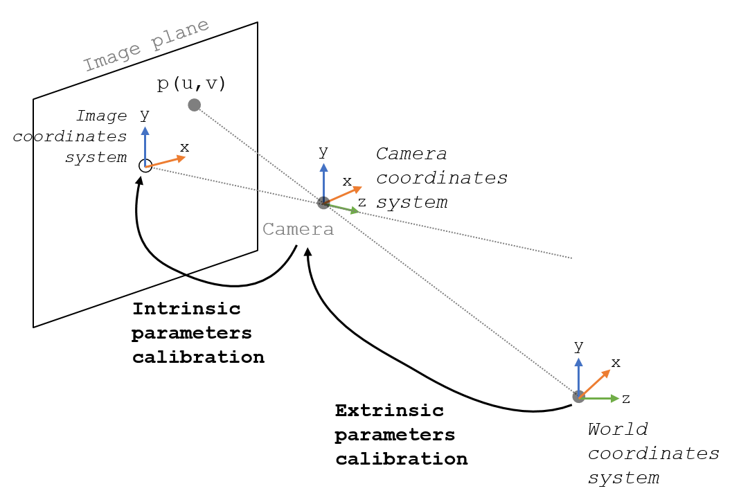
I. Intrinsic Parameters
Intrinsic parameters describe the internal characteristics of a camera, such as the focal length, optical center (principal point), and skew coefficient. These parameters define the mapping between 3D camera coordinates and 2D image coordinates. The intrinsic matrix, often represented as \(K\) \(K\), is used to transform 3D points into 2D homogeneous image coordinates.
- Focal length(\(f_x\) and \(f_y\)): The distance from the camera’s optical center to the image plane.
- Optical center (principal point) (\(x_0\) and \(y_0\)): The intersection of the camera’s optical axis with the image plane.
- Skew coefficient (\(s\)): The deviation from a perfect orthogonal grid of pixels, which is typically zero for most cameras.
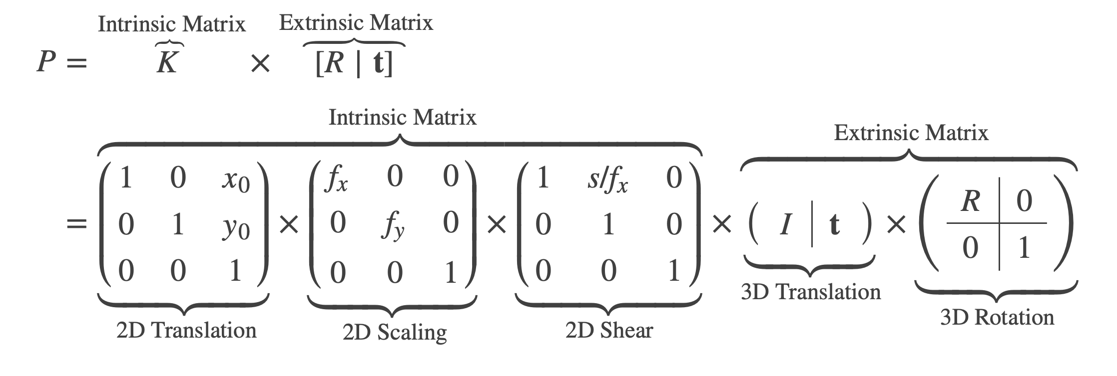
The intrinsic matrix \(K\) can be written as:
\[K = \begin{vmatrix} f_x && s && x_0\\ 0 && f_y && y_0 \\ 0 && 0 && 1 \end{vmatrix}\]II. Extrinsic Parameters
The extrinsic parameters consist of a rotation matrix (\(R\)) and a translation vector (\(t\)). The rotation matrix is a 3x3 matrix that defines the orientation of the camera’s coordinate system relative to the world coordinate system, and the translation vector is a 3x1 vector that defines the position of the camera’s coordinate system origin in the world coordinate system.
\[R = \begin{vmatrix} r_{11} && r_{12} && r_{13}\\ r_{21} && r_{22} && r_{23}\\ r_{31} && r_{32} && r_{33} \end{vmatrix}\] \[t = \begin{vmatrix} t_x\\ t_y\\ t_z \end{vmatrix}\]III. Combining Intrinsic and Extrinsic Parameters
The camera camera projection matrix \(P\) combines both intrinsic and extrinsic parameters to map 3D world points to 2D image points: \(P = K[R|t]\)
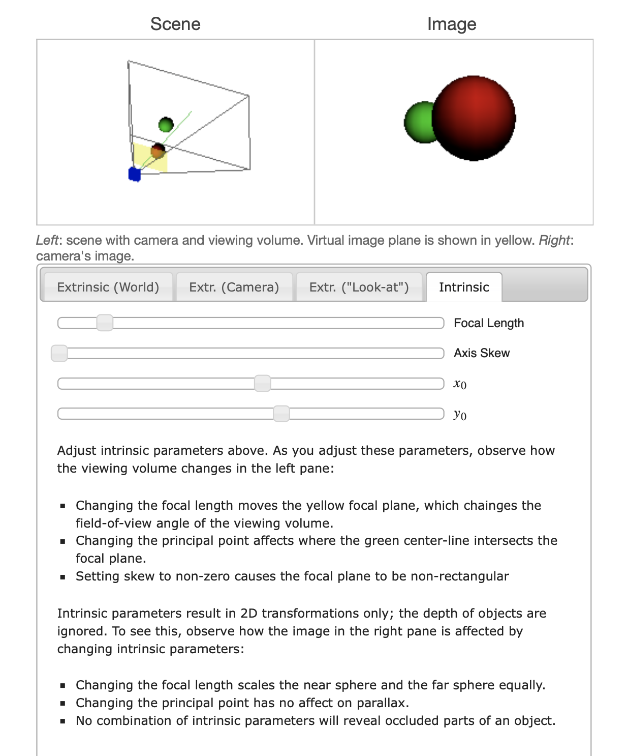
We can try the Perspective Camera Toy for more understand these parameters. This interactive toy shows how different camera parameters change the camera’s geometry and how a scene is rendered. This was originally built to supplement my upcoming articles exploring the intrinsic and extrinsic matrices; this is the standalone version.
IV. Camera Calibration
Camera calibration is the process of estimating both intrinsic and extrinsic parameters. The calibration algorithm calculates the camera matrix, which includes both intrinsic and extrinsic parameters, using correspondences between 3D world points and their 2D image points.
To calibrate a camera, you need to estimate its intrinsic and extrinsic parameters. Here’s a general outline of the process:
-
Prepare a calibration pattern: Use a well-defined pattern, such as a checkerboard, that you can easily detect in images.
-
Capture images: Take multiple images of the calibration pattern from different positions and orientations.
-
Detect pattern points: Identify the corners or features of the pattern in each image.
-
Find 3D world points: Assign 3D coordinates to the detected pattern points, assuming the pattern is placed in a known configuration (e.g., on a flat surface).
-
Estimate camera parameters: Use a calibration algorithm to estimate the intrinsic and extrinsic parameters that best map the 3D world points to the 2D image points.
More detail: https://www.mathworks.com/help/vision/ug/camera-calibration.html
V. Calculate the position of a 3D point in a pinhole camera
To calculate the position of a 3D point in a pinhole camera using the pseudo-inverse method, you can follow these steps:
-
Define the camera projection matrix, \(P\) , which combines the intrinsic and extrinsic parameters: \(P = K[R|t]\)
-
Given a 2D image point \(x = (u,v, 1)^T\) (in homogeneous coordinates), you can compute the corresponding 3D point \(X\) (up to scale) using the pseudo-inverse of the projection matrix: \(X = P^+ x\) where \(P^+\) is the pseudo-inverse of \(P\). Note that the resulting 3D point \(X\) is defined up to scale, meaning that it represents a ray in space passing through the camera center.
Position_3D_point_from_image_point.py
import numpy as np
import scipy.linalg as lin

# Define the camera projection matrix P
K = np.array([[f_x, 0,  c_x],
              [0,   f_y, c_y],
              [0,   0,    1]])

R = np.eye(3)  # Identity rotation matrix
t = np.array([tx, ty, tz])  # Translation vector

P = np.hstack((K, np.zeros((3, 1))))
P = np.dot(P, np.hstack((R, t)))

# Define a 2D image point x
x = np.array([u, v, 1])

# Calculate the 3D point X
X = np.dot(lin.pinv(P), x)

# X is defined up to scale, so you may want to normalize it
X = X / X[3]